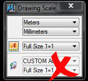
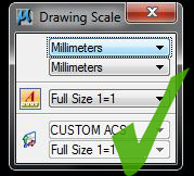
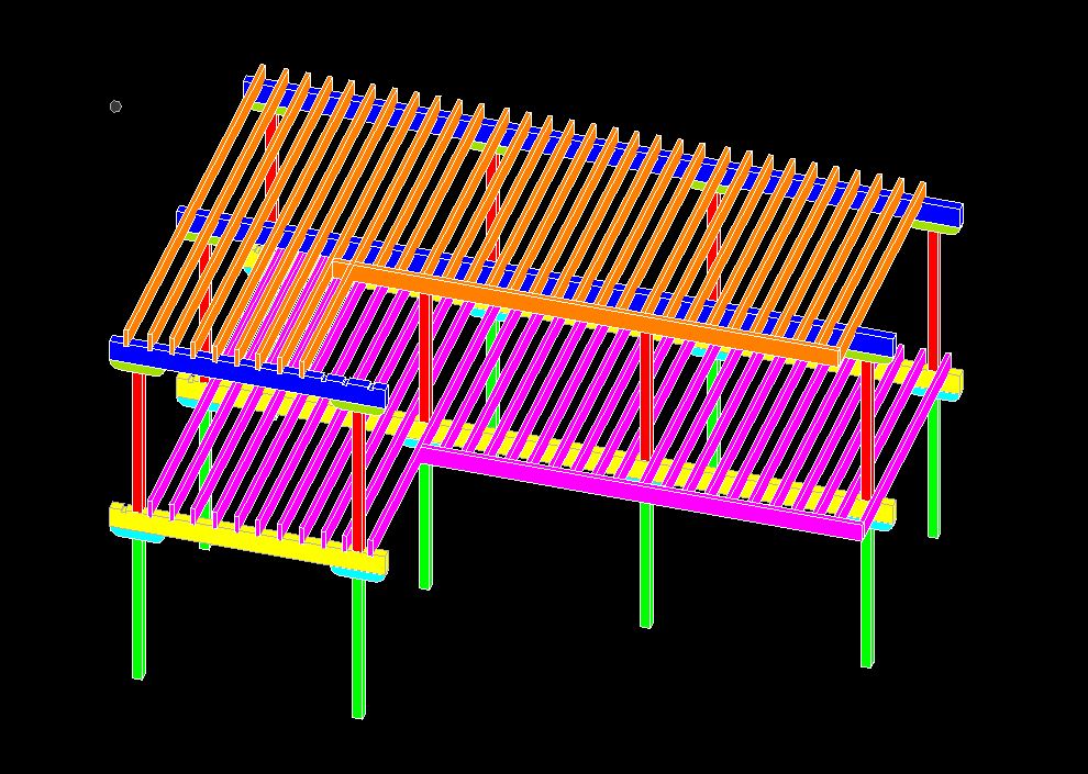
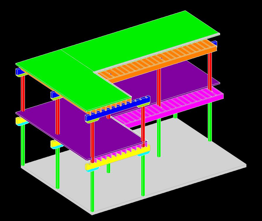
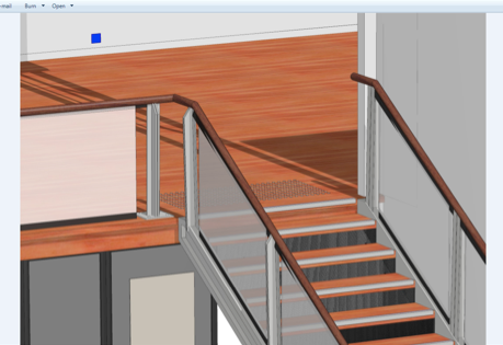
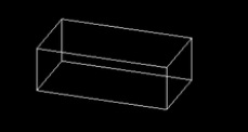
 Above I have used the slab tool. A lot of the elements that I will work with will begin with this. 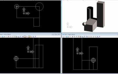 This image shows the four different views that micro station allows me to view and work in. They are top, front, side and isometric.. 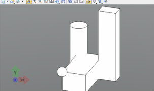 This image shows the same basic shapes but in a display mode of hidden filled lines. | Workshop one was basically getting used to a new computer program. I learnt the basic elements of micro station, including how to operate the four different views shown in the image to the side - Top, Front, Side and Isometric. Step One: The first step involved in workshop one was to open a new document and manipulate it so that it allows modelling in 3D. Step Two: Next it was time to familiarise myself with the basic functions and shortcuts available on micro station and to set the measurements to millimetres as opposed to metres. Step Three: Then it was time to actually start to model. At first working with each separate view was a bit tricky when it came to knowing which one to click. Once getting one shape down - a slab, which is a rectangular prism or a cube depending on how you model it - it was easy to place each correlating shape in terms of the slab. Step Four: Lastly, once all the shapes were placed on the page, it was time to experiment with the different display modes. This does not make that much difference in terms of the modelling but it definitely helps to see how the model is progressing and will give a very rough idea of how it is going to look once rendered. Changing the display mode can also come in handy when there is an overwhelming amount of lines as it can hide some of them. |
0 Comments
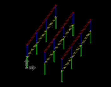
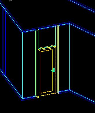
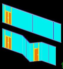
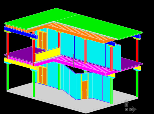
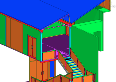
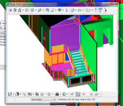
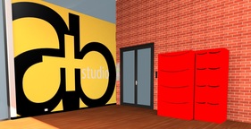
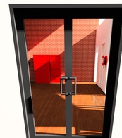
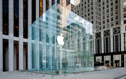 This weeks workshop was a lot different to the previous ones. We had demonstrate what we have learnt thus far in micro station in order to replicate a building in only 2 hours. I chose to replicate the New York Apple Store. I did not quite finish it within the 2 hours, but I managed to get most of the glass panels onto the exterior walls and was about to start the finishing touches of the building, including the door. Because the building works on a grid layout, I found adding elements such as the columns, beams and windows not too complicated to model. 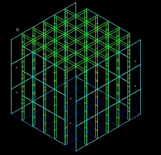
|